Guides / Design for Manufacture
Machining a Turntable Motor Pulley: Runout, Diameter and Speed
November 5, 2026
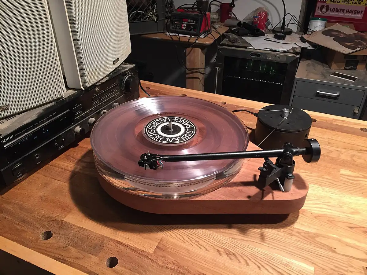
A turntable motor pulley sets the platter speed, so two things matter: its working diameter and how true the groove runs on the motor shaft. The diameter comes from the motor speed and the platter, and the runout is a drawing callout the shop has to measure. This guide gives the calculation, the fit and the checks to put in the RFQ for a belt-drive pulley.
Related parts are covered in turntable platter machining and tonearm component machining.
What the pulley does
In a belt-drive turntable the motor sits off-centre from the platter and an elastic belt connects it to the platter or a sub-platter. Reference sources say multi-speed designs move the belt between different-sized pulleys on the motor shaft, and that the elastic belt absorbs motor vibration that would otherwise reach the stylus. The pulley is therefore a speed gearbox: a small diameter turns the platter slowly and a larger step turns it faster.
Working out the diameter
The belt does not slip, so belt speed is the same at the pulley and at the platter rim. Platter rpm equals motor rpm times pulley diameter divided by platter diameter, both taken as working diameters where the belt actually rides.
Motor speed for a synchronous motor is 120 times the mains frequency divided by the number of poles, per the synchronous motor reference. A 4-pole motor gives 1500 rpm on 50 Hz and 1800 rpm on 60 Hz. The table below solves the pulley diameter for an assumed 300 mm working platter diameter (arithmetic only, not a design):
| Motor | Mains | Motor rpm | Pulley for 33⅓ rpm | Pulley for 45 rpm |
|---|---|---|---|---|
| 4-pole | 50 Hz | 1500 | 6.67 mm | 9.00 mm |
| 4-pole | 60 Hz | 1800 | 5.56 mm | 7.50 mm |
| 12-pole | 50 Hz | 500 | 20.00 mm | 27.00 mm |
| 12-pole | 60 Hz | 600 | 16.67 mm | 22.50 mm |
Three things follow for the drawing.
- The mains frequency belongs on the drawing. The same motor spins 20% faster on 60 Hz, so a pulley cut for 50 Hz is wrong for a 60 Hz market. The fix is a second pulley for that market or a speed controller, and the brand decides which.
- The 45 rpm step is 1.35 times the 33⅓ step. The ratio 45 divided by 33.33 is fixed, so both steps on a stepped pulley must be cut from one setup and one measurement, not two separate ones.
- The working diameter is not the metal diameter. The belt has thickness and stretches, so it rides at a slightly larger diameter than the groove surface. The designer should confirm each step with a strobe on the first prototype and give the shop the corrected size.
A smaller pulley is also less forgiving. A 0.01 mm diameter error is 0.05% on a 20 mm pulley and 0.15% on a 6.67 mm pulley.
Runout turns into speed error
If the groove runs off-centre by an eccentricity e, the belt contact radius changes by plus and minus e once per motor revolution. The speed ripple is about e divided by the pulley radius, which equals the total indicator reading (TIR) divided by the diameter. Run-out is measured with a dial indicator pressed on the rotating part, and TIR is the full indicator movement.
| Groove TIR | 6.67 mm pulley | 10 mm pulley | 16 mm pulley | 20 mm pulley |
|---|---|---|---|---|
| 0.005 mm | 0.075% | 0.050% | 0.031% | 0.025% |
| 0.010 mm | 0.150% | 0.100% | 0.063% | 0.050% |
| 0.020 mm | 0.300% | 0.200% | 0.125% | 0.100% |
These are peak, worst-case values before the belt and the platter’s inertia smooth them out, so treat them as a way to rank designs, not as a prediction of what a listener hears. For context, the wow and flutter reference quotes about 0.02% weighted for professional tape machines and about 0.08% for high-end cassette decks, and lists IEC 386 and DIN 45507 as the weighting standards. It also says turntables suffer mainly from slow wow and that listeners find flutter most objectionable around 4 Hz. The ripple from a pulley appears at the motor rotation rate, 25 Hz at 1500 rpm, so the weighting counts it less than a once-per-platter-turn error. It still sets a floor.
No public standard gives a pulley runout limit. The practical route is to let the designer set a speed budget from the wow and flutter target, convert it with the table, and ask the shop to report what it holds.
Bore fit adds runout
The groove can be perfectly round and still run out if the pulley sits loosely on the motor shaft. A diametral clearance c lets the pulley axis sit up to c/2 off the shaft axis, which is a TIR of up to c at the groove. Take a 5 mm shaft, which falls in the “over 3 to 6 mm” size band of the ISO fit tables:
| Fit | Bore | Shaft | Result |
|---|---|---|---|
| H7/h6 | 0 to +0.012 mm | 0 to −0.008 mm | Clearance 0 to 0.020 mm |
| H7/k6 | 0 to +0.012 mm | +0.001 to +0.009 mm | Clearance 0.011 mm to interference 0.009 mm |
| H7/p6 | 0 to +0.012 mm | +0.012 to +0.020 mm | Interference, 0 to 0.020 mm |
The page lists H7/g6 as a sliding fit, H7/k6 as a fit with negligible clearance or interference and H7/p6 as a press fit. A set screw pulley on an h6 shaft can add up to 0.020 mm of TIR before the groove tolerance is counted. If the motor allows it, a transition or light press fit with a clamp screw or adhesive keeps the pulley centred. Measure the real motor shaft, since its size and tolerance come from the motor maker, not from your pulley drawing.
How the shop holds the runout
- Cut the bore and the belt groove in one chucking on a CNC lathe, or finish the groove on a mandrel that sits in the finished bore. Re-chucking the part to cut the groove is the usual source of eccentricity.
- Call out groove runout to the bore as datum A, for example “TIR 0.01 mm to A”, and ask for the measured value on the first article report. Datum practice is in drawing callouts for cosmetic faces and stacking of tolerances in tolerance stacks for audio products.
- State the step diameters with a tolerance, such as plus and minus 0.01 mm, and ask for a measurement of each step, not a sample of one.
- Deburr the groove edges so the belt does not fray, but do not round the groove walls without agreement, since that moves where the belt rides.
Material and finish
Aluminum, brass and stainless all turn well. Pick by appearance and by how much mass the designer wants on the motor shaft. A coating changes the diameter, because anodizing grows half the coating thickness outward on each surface, so a 10 µm coat adds 10 µm to the diameter. On a 10 mm pulley that is about 0.1% speed. Either leave the groove bare or state the final diameter after coating, as in anodizing colour match for hi-fi parts. A visible pulley may also be polished or blasted, but the groove itself should keep the finish the designer tested with.
What to put in the RFQ
- STEP model and 2D drawing with the bore, each step diameter and the groove runout to bore
- Mains frequency and motor type, so the shop can see why the diameters are what they are
- Motor shaft diameter and tolerance, and how the pulley is fixed (set screw, clamp or press fit)
- Material and finish, and whether the diameter is final before or after coating
- Quantity per run and annual volume. Pulleys are small bar-fed parts, so price per piece drops quickly with quantity, see MOQ and lead time
- First article report with measured runout, see first article inspection
Send the drawing through the RFQ form and we match it with up to 3 shops that turn small precision parts, with a reply within 24 business hours.
Sources
- Belt-drive turntable, Wikipedia
- Synchronous motor, Wikipedia
- Wow and flutter measurement, Wikipedia
- Run-out, Wikipedia
- Engineering fit, Wikipedia
- Anodizing, Wikipedia
Frequently asked questions
How do you calculate the diameter of a turntable motor pulley?
Platter speed equals motor speed times the ratio of pulley to platter working diameters. So pulley diameter equals platter diameter times 33.33 divided by motor rpm. A 4-pole motor on 50 Hz runs at 1500 rpm, so a 300 mm working platter diameter needs about 6.7 mm. Confirm on a prototype with a strobe, because belt thickness shifts the working diameter.
How much runout is acceptable on a motor pulley?
No public standard sets a figure. Speed error from runout is roughly the total indicator reading divided by the pulley diameter, so 0.01 mm on a 10 mm pulley is about 0.1% peak. The designer sets a target from the wow and flutter goal, then the shop reports what it can actually hold.
Why does a pulley made for 50 Hz not work on 60 Hz mains?
Synchronous motor speed follows mains frequency. A 4-pole motor runs at 1500 rpm on 50 Hz and 1800 rpm on 60 Hz, which is 20% faster. The pulley diameter must shrink by the same ratio, or a speed controller must be used. State the mains frequency on the drawing.
Does anodizing a motor pulley change the speed?
Yes. Anodizing grows half the coating thickness outward on each surface, so the diameter increases by the full coating thickness. A 10 micron coat adds 10 microns to the diameter, about 0.1% on a 10 mm pulley. Say whether the drawn diameter is before or after coating.
Need a quote for this part?
Send the drawing. We match you with up to 3 shops and reply within 24 business hours.
Get matched with an audio parts shop