Guides / Design for Manufacture
Audio Knob to Shaft Fit: Choosing a D-Bore, Knurled Spline or Set Screw
November 2, 2026
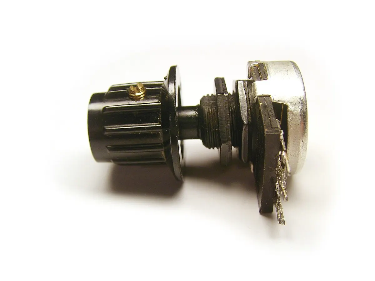
An audio knob fixes to its shaft in one of three ways: a set screw on a round or flatted shaft, a flat inside the bore that matches a D-shaft, or a knurled spline that pushes on. The choice is set by the control the brand has bought, and by whether the pointer position must be adjustable at assembly. The rest is bore tolerance, screw position and what the finish does to the hole.
For the knob itself see CNC volume knob manufacturing.
The three fixing methods
| Fixing | Fits | Strength | Weak point | Put on the drawing |
|---|---|---|---|---|
| Round bore with set screw | Round shafts, flatted shafts, T18 toothed shafts | Pointer can be set at assembly | Screw point marks a round shaft | Bore size and tolerance, screw size and angle to the pointer |
| D-bore with set screw | Flatted D-shafts | Flat fixes the angle before the screw tightens | Needs a matching flat, so only one shaft type | Flat depth, flat width, flat angle to the pointer |
| Knurled or splined bore | Toothed T18 shafts | Pushes on, no screw on the visible face | Only suits toothed shafts, little adjustment | Tooth count, major and minor diameters, bore depth |
The machined aluminum knob on one electronics retailer’s page is listed for any 6 mm shaft and names T18, round and D-shaft types. It has a 6 mm shaft hole, a set screw tightened with a 2 mm hex wrench and a 20 mm outside diameter (listing). A sister product from the same seller cannot go on round shafts of 6.3 mm, and the page tells buyers to check the control with calipers or the datasheet (listing). Two points follow. First, 6 mm and 6.3 mm shafts are both in use and they do not swap. Second, a knob drawing must name the shaft it is made for, not just a diameter.
How each method grips
Set screw. A set screw is the most common fixing, and the cup point is the usual point type. A flat or detent milled where the point lands reduces slipping and raises load capacity. Hardened screws on a plain shaft leave a circular mark that adds holding power but is a cosmetic blemish and can leave raised metal that complicates removal, so the flat is the remedy (set screw reference). A set screw works best when the shaft is softer than the screw (shaft collar reference). A knurled cup point resists loosening under vibration but should not be reused, since tightening deflects its cutting edges.
D-bore. The flat inside the bore sits on the flat of the shaft, so the knob angle is fixed even before the screw bites. The flat position relative to the pointer line is the dimension that counts. Take the flat depth and width from the control’s own drawing, because makers differ.
Knurled or spline. A spline is a ridge or tooth on a shaft that matches a groove in a mating piece and transfers torque. Serrated splines have V-shaped sides and are used on small shafts (spline reference). Knurling displaces material rather than removing it (knurling reference). A toothed bore is a different operation from turning, so ask the shop how it cuts the teeth, for example by broaching in the knob or by pressing in a toothed insert.
Bore tolerance, from ISO fits
Tolerances come from the ISO fit tables. In the “over 3 to 6 mm” size band, which includes a 6 mm shaft:
| Combination | Bore | Shaft | Result |
|---|---|---|---|
| H7/h6 | 0 to +0.012 mm | 0 to −0.008 mm | Clearance 0 to 0.020 mm |
| H7/g6 | 0 to +0.012 mm | −0.004 to −0.012 mm | Clearance 0.004 to 0.024 mm |
| H7/k6 | 0 to +0.012 mm | +0.001 to +0.009 mm | Clearance 0.011 mm to interference 0.009 mm |
H7/g6 is listed as a sliding fit, and H7/k6 as negligible clearance or interference. For a set screw knob a sliding fit is right: it goes on by hand and the screw takes up the play. For a push-on spline or a bonded insert, a transition or light press fit is the aim. These are the ISO sizes for the bore, but the shaft is whatever the control maker delivered, and its tolerance is not always on the datasheet. Measure a sample before releasing the drawing.
What play does to the look
A diametral clearance of 0.020 mm lets the knob axis sit up to 0.010 mm off the shaft axis, and over a 10 mm engagement it allows a tilt of about 0.11°. At the rim of a 40 mm knob that is about 0.04 mm, so the clearance itself is invisible. What the eye picks up is the gap to the panel and the pointer line. A longer bore engagement reduces tilt, so give the bore enough depth. A pointer line that is off by 1° moves 0.35 mm at a 20 mm radius, which is easy to see against a printed scale, so tolerance the screw or flat angle to the line and have the first article checked, see first article inspection.
What the finish does to the bore
- Anodize. Coating grows half the thickness out of each surface and half into it (anodizing reference), so a 10 µm coat shrinks a bore by 10 µm. On an H7 bore with a 12 µm tolerance band that is nearly the whole band. State whether the bore is final before or after anodizing, mask it, or ream after finish. See anodizing colour match for hi-fi parts.
- Set screw thread. A tapped hole in a thin aluminum wall strips easily and the coating grows into a thread, as covered in threads in anodized chassis. Give the screw boss enough wall and tap after anodizing.
- Polishing and blasting. Do these before the bore is finished or protect the bore, since abrasive media can round the bore edge and change the lead-in.
- Screw hidden or visible. A screw on the side of a knob is visible. Hide it with a cap, put it on the back or choose a spline, and show that choice in the drawing, see drawing callouts for cosmetic faces.
What to put in the RFQ
- STEP model and 2D drawing, with the shaft maker, part number and shaft type
- Bore diameter and tolerance, with a note on whether it is final after finish
- Flat or tooth data copied from the control’s drawing, not from a photo
- Screw size, point type, position and angle to the pointer line
- Bore depth and chamfer at the mouth
- Finish and whether the bore or screw hole is masked
- A sample shaft or control with the first order, so the shop can try the fit
- Quantity per run and yearly volume
Send the drawing through the RFQ form and we match it with up to 3 shops that turn and finish small knobs, with a reply within 24 business hours.
Sources
- Anodized aluminum machined knob listing, 20 mm
- Anodized aluminum machined knob listing, T18 or D-shaft
- Set screw, Wikipedia
- Shaft collar, Wikipedia
- Spline (mechanical), Wikipedia
- Knurling, Wikipedia
- Engineering fit, Wikipedia
- Anodizing, Wikipedia
Frequently asked questions
How do I fit a knob to a 6 mm potentiometer shaft?
Match the knob bore to the shaft type first. A round bore with a set screw fits a round shaft, a D-bore fits a flatted shaft, and a knurled or splined bore fits a toothed shaft. Check the shaft with calipers, because a 6 mm bore does not fit a 6.3 mm round shaft.
Should a machined knob use a set screw or a spline fit?
A set screw fits more shaft types and gives an adjustable pointer position, but it marks the shaft unless the shaft has a flat. A spline or knurled bore pushes on without tools and keeps its position, but only suits toothed shafts, so it limits which controls the brand can use.
What bore tolerance should an audio knob have?
For a 6 mm shaft, an ISO H7 bore runs 0 to plus 0.012 mm. Against a shaft ground to h6 that is a clearance of 0 to 0.020 mm, which is a sliding fit. Confirm the real shaft size first, since pots come in different diameters and tolerances.
Does anodizing change the knob bore size?
Yes. Anodizing grows half the coating thickness inward and outward on each surface, so a 10 micron coat makes the bore 10 microns smaller. Say whether the bore size on the drawing is before or after anodizing, or mask the bore or ream it after finishing.
Need a quote for this part?
Send the drawing. We match you with up to 3 shops and reply within 24 business hours.
Get matched with an audio parts shop